SIR Explained
SIR is a measurement of the resistance across a PCB surface. Component pads and PCB tracks are isolated from each other. Hence the resistance between these features should be very high. IPC J Std 001 sets a resistance limit of 10⁸Ω, which means all resistance values measured in a SIR test must be above this limit.
Resistance values will drop towards this 10⁸Ω value if a water film forms on the PCB surface. A water film can form when the temperature and humidity are raised above the ambient, the SIR test conditions of 40°C/90%RH and 85°C/85%RH will definitely lead to the formation of an adsorbed water film. Water is not particularly conductive, but absorption of CO₂ from the air forms carbonic acid (H₂CO₃) that increases the conductivity. However, what increases the conductivity far more significantly are residues from the manufacturing processes. These residues dissolve to form far more ionic material in the water film than absorption of gases. The SIR test is sensitive to this residue effect which if severe can easily drop the resistance to below the 10⁸Ω, and hence leading to a failure of the test vehicle.
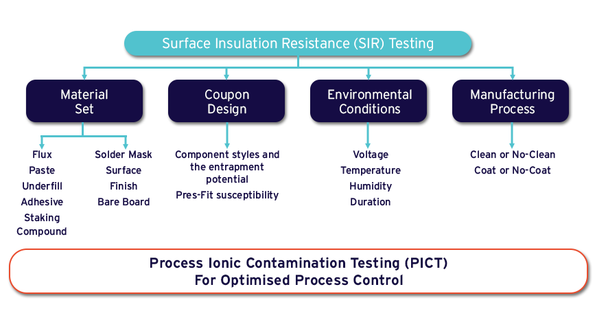
A SIR test is carried out to determine the residues from any number of sources, fluxes, solder pastes, coatings, cleaning processes, components, and there are many more examples. There are a number of SIR tests in the standards and a specific one can be chosen to meet the particular needs of a characterisation study or even an OE study.
What does a SIR test comprise?
There are two key elements to a SIR test, there is the SIR test measurement equipment and a damp heat chamber; there will also be connecting cables between the SIR equipment and the test boards which will be in the damp heat chamber. In any setup there are several issues that must be considered.
Electrical Noise:
SIR measurements are made up to 10¹²Ω, which equates to very low currents of a few pico-amps. Such low currents can be very problematic if exposed to electromagnetic interference (EMI). Hence location can critical, and a SIR setup is best located in a laboratory away from manufacturing equipment and heavy electrical installations.
Cabling:
The connection from the test vehicles to the SIR equipment needs to properly shielded which typically entails the use of an earthed braided shroud. This protects the cables from EMI effects.
Rack:
The test vehicle fixture should hold the test vehicles in a stable position, parallel to each other to facilitate good access to the circulating volume of air. The test vehicle is typically referred to as a rack. Using a rack allows connectors to be used, which prevents the need for soldering. Soldering connecting wires to the test vehicle requires great care to avoid leaving any residues. Good practice is covered in the IPC guidance documents 9201, 9202 and 9203.
Chamber:
The damp heat chamber needs to be of sufficient volume, typically greater than 10 times the volume of the rack. Also the rack should be at least 150mm away from the chamber walls. As failure to meet the set damp heat conditions increases, so will the likelihood of not achieving the temperature humidity condition on the test vehicle. Studies have shown that high humidities, ≥ 85%, the absorbed water layer thickness is extremely sensitive to humidity. Hence as this unsatisfactory condition arises the SIR value will deviate significantly from the true value.
Coupon Quality:
The coupon, or test vehicle, needs to be manufactured to the same standard as the production boards. Inferior quality can lead to miscellaneous results. When the test vehicle includes components, such as the IPC B52, care must be exercised when using simulated components manufactured from PCBs. Simulated processor chips that maybe emulate BGA, QFN, or WLP can behave very differently to the component they are replicating.
Standards:
IPC and IEC have test methods to follow which give the test method and coupon designs. These directly relate into J Std 001, and hence OE. This connection between the test methods is important in evidencing that a recognised route has been taken in producing OE.
Gage R&R:
In developing standards the SIR method has been tested and Gage R&R has been proven. The Gen3 AutoSIR was a key part of this international study and hence can claim to have been proven in demonstrating Gage R&R. This is an important verification that the AutoSIR meets this key requirement. Reference: A Gage Study of an Intercomparison Evaluation to Implement the Use of Fine-Pitch Test Patterns for Surface Insulation Resistance (SIR) Testing of Solder Fluxes.
Snap-off Coupon:
Having part of your production board that can be removed for testing has a long history. This sacrificial part of the production board is designed as a test vehicle to emulate the most susceptible components on the production board. For most OEMs this is unacceptable, as in the majority of cases you are building something that is being immediately scrapped. This makes no economic sense. Furthermore, for the SIR testing of complex integrated circuits, such as processors, a dummy component must be used. Hence, the inventory on the snap-off test vehicle necessarily diverges from the main production board. Hence, batch variations on the production board will not be characterised in the snap-off test vehicle. Hence the PICT test is the test of choice for monitoring production quality.
A SIR test is carried out to determine the residues from any number of sources, fluxes, solder pastes, coatings, cleaning processes, components, and there are many more examples. These are identified in the chart below. There are a number of SIR tests in the standards and a specific one can be chosen to meet the particular needs of a characterisation study or even OE study.