SIR Further Information
SIR testing: this is a resistance measurement between two conductors. Typically this is between two interlinked parallel comb patterns, but can also be measurements between rows of parallel component pads that are isolated.
Manufacturers of many process materials used in the production of electronic assemblies such as solder flux, paste and wire, solder resists and masks, conformal coatings etc., must qualify their product using SIR. For this, there are many Standard test methods.
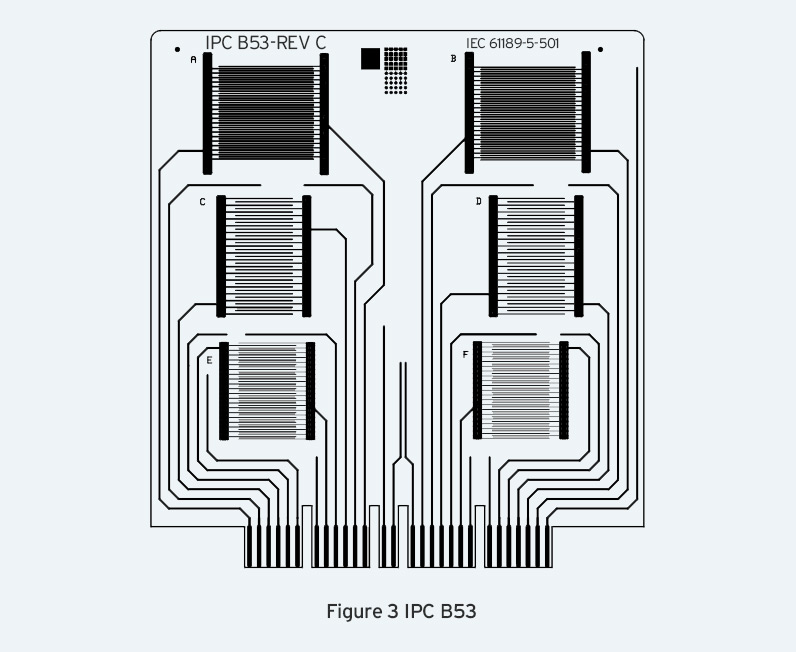
Historically, a 5 point test pattern was used as per GR-78-CORE from Tellcordia Technologies (Formerly Bellcore). Subsequent research demonstrated that automated measurement equipment was able to conveniently handle multiple 2 point patterns on test coupons such as IPC B24, B25A and most recently B53.

To answer the need for a new Standard Test Coupon the IPC B53 was created by GEN3 that incorporates 3 x 2 patterns of 400µm x 500µm (IPC B24) 318µm x 318µm (IPC B25 and B25A) and 400µm x 200µm to reflect finer pitch products.

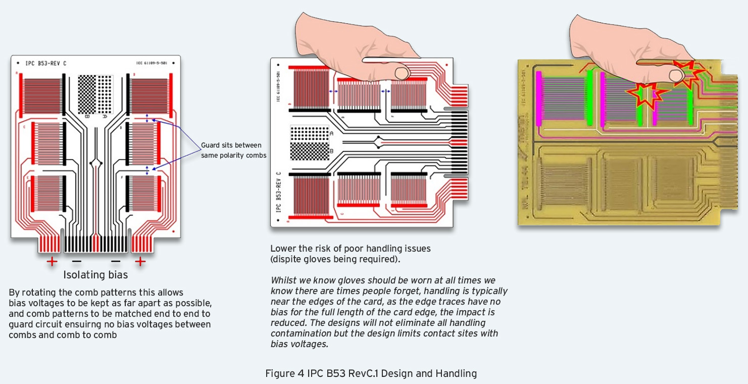
The IPC B53 test coupon has an important number of special design features to enhance their usability. (See Figure 4)

Given that a typical electronic circuit assembly undergoes at least 20 individual process steps, each using highly ionic process materials, understanding the electrochemical compatibility between them as a Material Set, is essential.
At each manufacturing process step, the presence of components creates a far greater opportunity for process residue entrapment. In research work carried out by NPL they created a new test vehicle, being the coupon plus components, named the TB57 (See Figure 5).

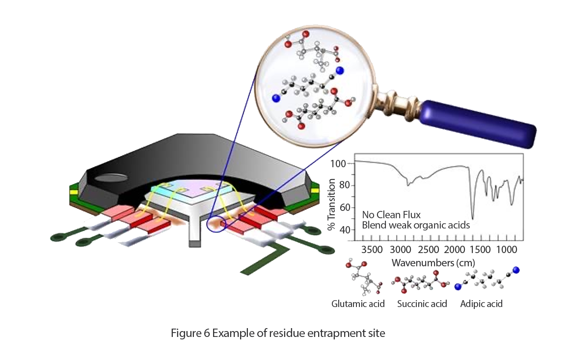
SIR comb patterns can be located under components in the very area where the residue entrapment probability is highest (See Figure 6). Its design was to consider a “worst case” for process residue entrapment. It was never intended to consider circuit design constraints as the test was simply to assess the Electro-Chemical compatibility of the chosen Material Set. This coupon has subsequently been evolved into the IPC B52 (See Figure 7).


The International Standard test method is IEC 61189-5-502. In this test vehicle the assembly is placed in a damp heat environment, with an applied voltage and the resistance is monitored for 168 hours (one week). In this test the resistance shall not drop below 10⁸Ω.
If the user is following IPC, then it is important to refer to the following documents:
IPC 9201 – SIR Test Handbook
IPC 9202 – Material and Process Characterization/Qualification Test Protocol for Assessing Electrochemical Performance Using the IPC-B-52 Test Assembly
IPC 9203 – Users Guide to IPC-9202 and the IPC-B-52 Standard Test Vehicle
IPC-WP-019 – An Overview on Global Change in Ionic Cleanliness Requirements
The construction of this test board follows that of the product as closely as possible, but any test vehicle must use dummy components with all internal connections open, i.e. there is no die and no connections between the lead-frame pads.
Note that research is now underway at 2 different voltage levels to reflect current industry needs:
High Voltage - >300V to 1000V
Low Voltage - <2V with 75µm pattern spacing (HDPUG)
Research is showing that the test duration may need to be extended to around 1000 hours.